MLDAC-4 Digital to Analog Converter 4 inputs. Allows to use one analog input as 4 digital inputs.
MLDAC-4 SETUP
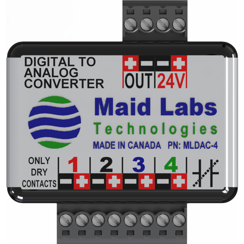
Digital to Analog Converter MLDAC-4 transforms 4 digital dry contact inputs into one output voltage that is unique to the status of its 4 digital inputs.
Version 1 requires dry contacts. Version 2 allows dry and ground contacts.
The Volucalc Hybrid voltage output 12 VDC out is related to the voltage powering the Volucalc and is not necessary 12 VDC. Since Maid Labs is supplying a 24 VDC power supply, the voltage output of the Volucalc is around 24 VDC.
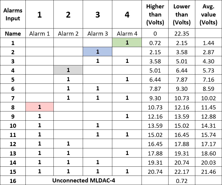
This table shows every possible alarm combination, the voltage range for each combination (Higher and Lower than columns) and the actual voltage output of the device for each combination (Avg. value column).
The Volucalc voltage output generates around 22.35 VDC when powered by a 24 VDC power supply. This voltage is not greatly affected when powering a cellular modem and a level sensor.
When no alarm is activated, the voltage is close to 22.35 V.
When the device is disconnected (line 16th), the voltage is lower than 0.72 V. So, to create an alarm indicating that the MLDAC-4 is disconnected from the Volucalc, the alarm settings need to monitor for a voltage that is lower than 0.72 V. This alarm could be called “MLDAC-4 Disconnected.”
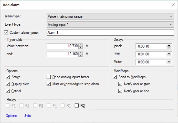
To detect an alarm on input #1 (8th combination), the alarm setting must be set for a voltage range between 10.73 V and 12.16 V. Since the MLDAC-4 generates 11.45 V when alarm #1 contact is closed, Volucalc detects it and generates an alarm for it. This alarm could be called “Alarm 1.”
If you know that multiple alarms are very unlikely, then you might not need to configure all possible combinations and only set lines 1, 2, 4 and 8. If you configure them all, it will look like this if all alarms are ON at the same time. The 15th combination indicates to set a voltage range between 20.74 V and 22.17 V. This alarm could be called “Alarm 1, 2, 3, 4 ON.”
To set up the alarms using the MLDAC-4, follow these instructions.
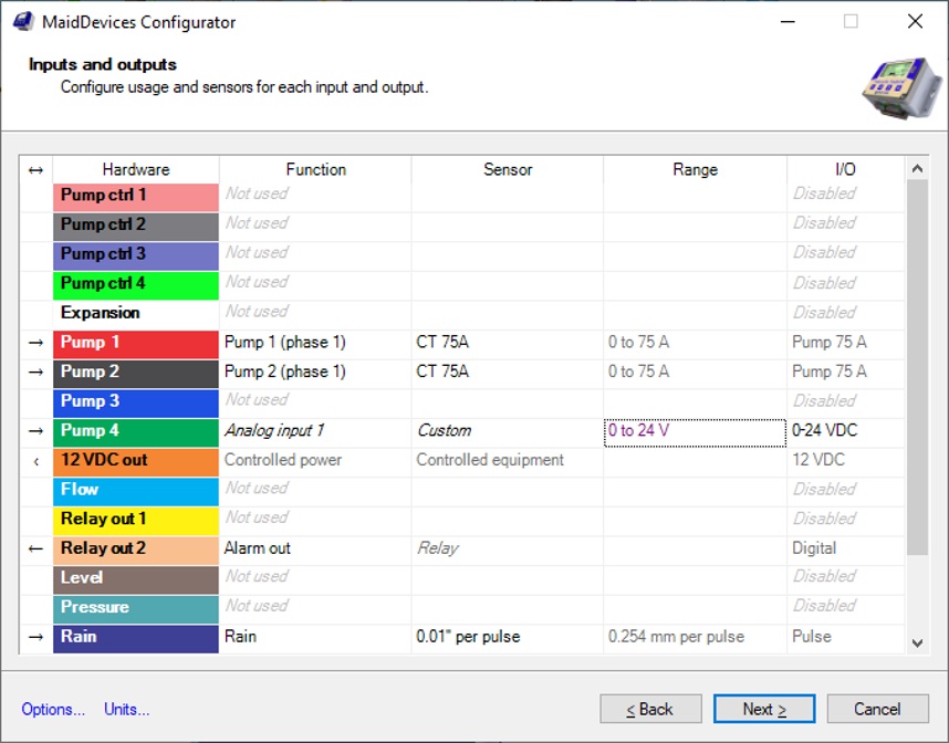
In the Inputs and Outputs dialog of the Maid Device Configurator, select the unused analog input on which the Digital to Analog Converter MLDAC-4 will be installed.
In this example, Input Pump #4 is used. The Function name is Analog input 1 and the Range and I/O are set at 0-24 V.
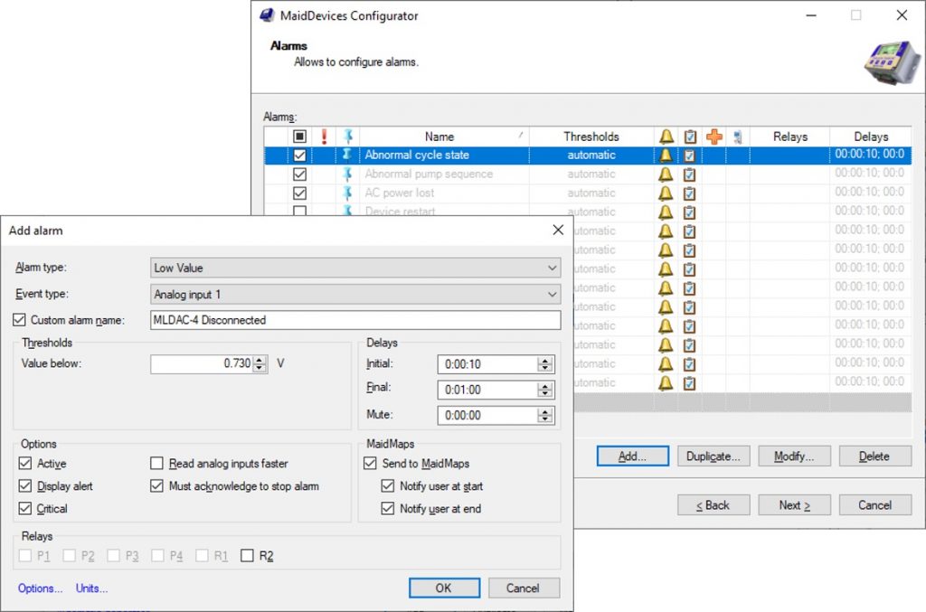
To create an alarm about a disconnected MLDAC-4 module, do the following:
In the Alarm dialog, press Add…
In the Add alarm dialog, set Alarm type as Low Value.
In the Event type, select the input attributed to the MLDAC-4.
To change the name of the alarm, check the box Custom alarm name and give it a meaningful name.
In this case, a voltage below 0.73 V means the MLDAC-4 module is not connected. When it is connected, it reads 22.35 Volts when all inputs are off.
In the Delays section:
Initial delay means the alarm must meet the condition for this delay period before the alarm is generated.
Final is the delay before the alarm is considered ended after the value is not in the threshold condition.
Mute is the delay before it’s possible to regenerate this alarm. So if only 1 alarm of this type per day is needed, it’s possible to set the mute value to 24 hours.
To set the Alarm #1 (8th line of the above table), set it up this way:
Of course, change the name to suit your needs
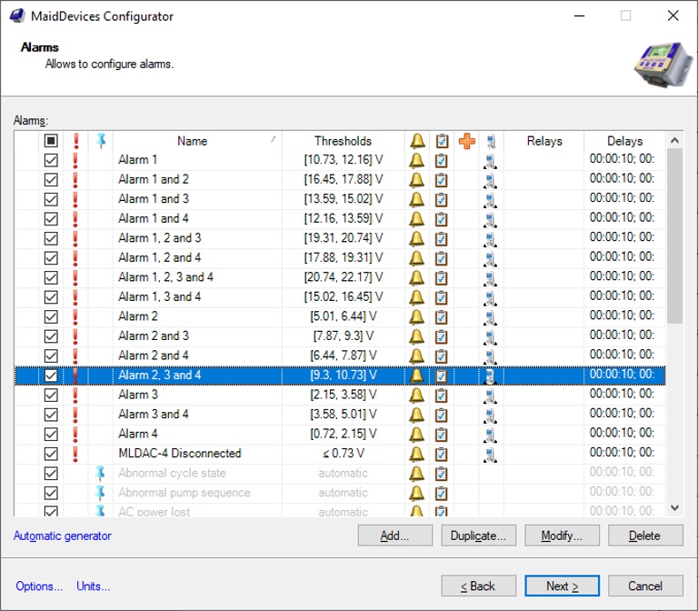
If you set them all, it will look like this. I used the Duplicate … function so the Alarm type, Event type and Name are copied. Only the voltage settings and the alarm names have to change to reflect the multiple alarms.
Individual alarms should be more detailed.
A configuration file is available with all 15 alarm settings for the MLDAC-4. To use the preconfigured file, in the Maid Device Configurator, select Create from an existing file and adjust the parameters to your needs.
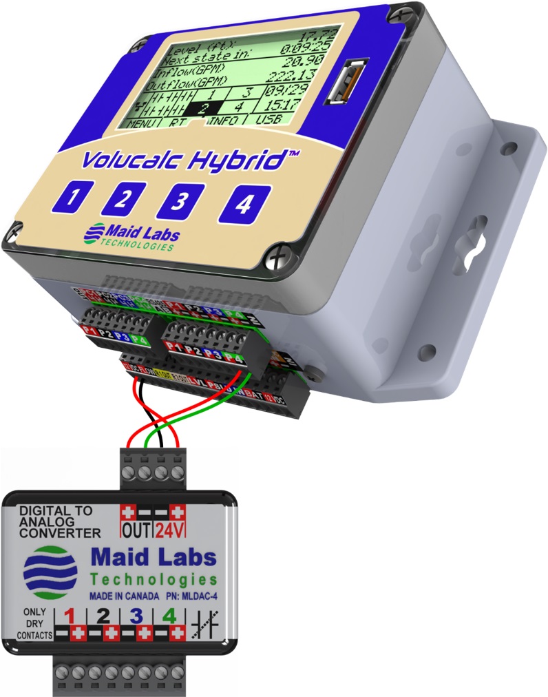
To connect the MLDAC-4 to the Volucalc:
Be sure to connect positive (+) to + and Negative (-) to -.
Connect the 12 VDC Output of the Volucalc (left end of the bottom connector) to the 24 V input of the MLDAC-4.
Connect the OUT of the MLDAC-4 to one of the six analog inputs of the Volucalc.
In this example, the input usually used by pump #4 is used for the digital alarms.
Negative is usually a black wire but it was not easy to see on this image for the analog input, so green was used.